Design
Amplification
Stage 1: Deciding on an amplification method
As the project is targeted at point of care applications, Polymerase Chain Reaction (PCR), one of the more common amplification methods, cannot be used. PCR machines require an active power supply and the equipment. As we had always taken PCR for granted, we had to do some research before we knew how we wanted to tackle our amplification system. And even when we did start finding alternatives, for a while we called them ‘PCR without PCR’.
We did find a solution, in the form of the Hybridisation Chain Reaction (HCR). We read about linear HCR, which we described in the project section. And then we found out about non-linear HCR. Hsing et al. (2014) successfully created a second order HCR system[5], which was published in the Journal of the American Chemical Society (JACS).
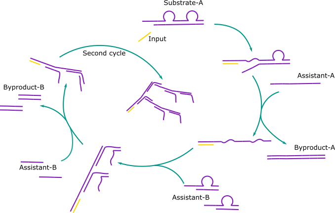
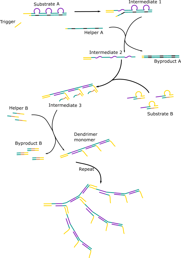
In their system, an input binds to a double stranded sequence called substrate-A. This causes the smaller strand of substrate-A to be displaced and with the help of another single stranded sequence, assistant-A, is displaced altogether. This leave the input-substrate-A complex with a long single stranded toehold. Two double stranded complexes, called substrate-B, bind to the two identical sections on the toehold. This causes the smaller strand to displace and detach completely with the help of assistant-B. This forms a dendrimer monomer, with two single stranded toehold complementary to the toehold of substrate A. And hence the process repeats.
This method suited almost all of our needs. The only modifications we would need to make were a system that could easily be adapted for different viruses and a system that amplified more.
Stage 2: Reproducing the Hsing et al. (2014) results
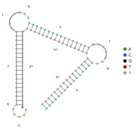
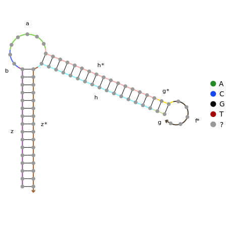
To ensure that this system works with different sequences, it is necessary to model the structures using online nucleic acid design software. NUPACK offers both design and analysis software and hence is ideal for reproducing the Hsing et al. (2014) complexes and design our own.
Click to view the NUPACK code for stage 2.
Click to view the 2nd order sequences.
Stage 3: Adaptor system
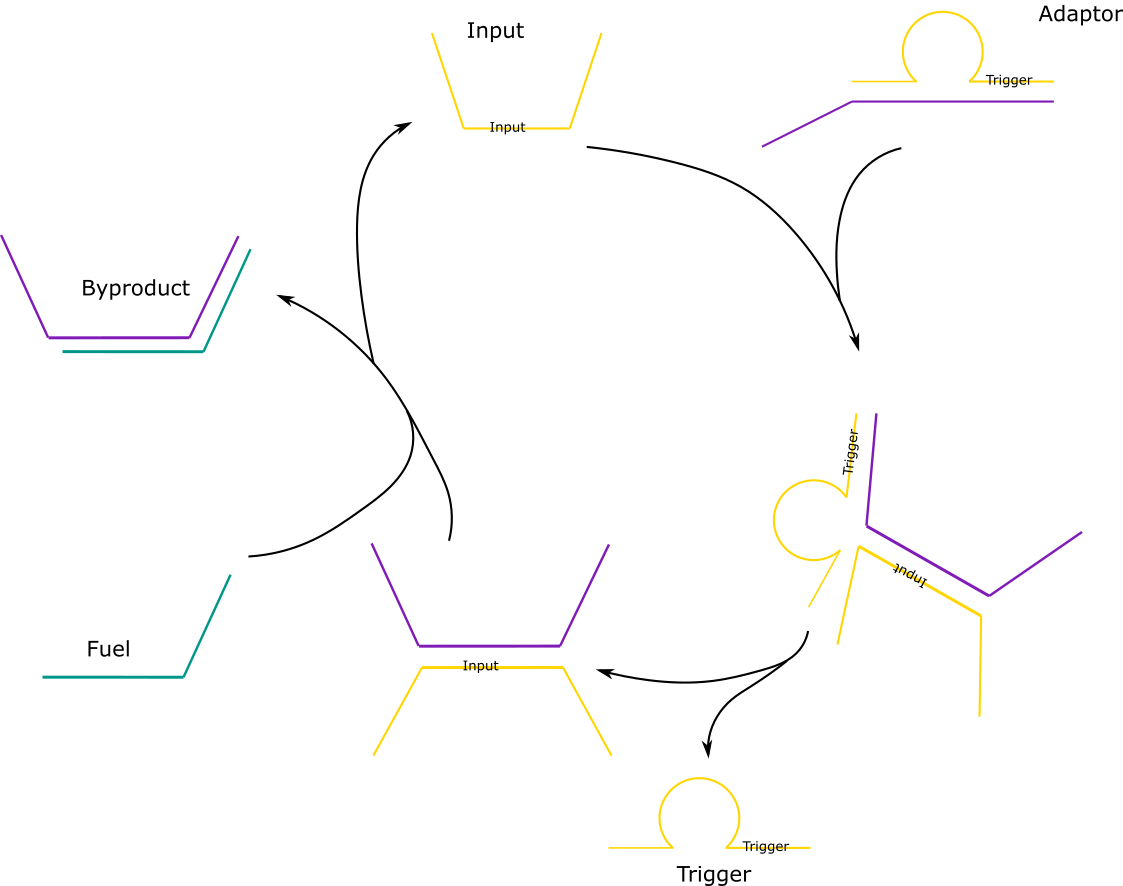
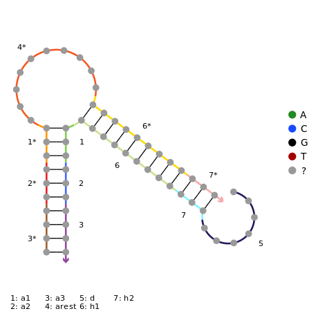
In order for the amplifications system to be easily adaptable to any virus, an adaptor system is introduced. The adaptor consists of the trigger strand, which would be used in the dendrimer, and a partially complementary strand which we termed “the lock” which forms a loop, as per the diagram below. It involves an input, which will be the viral DNA in the final system. The input binds to a toehold of the adaptor. This should induce toehold mediated displacement, meaning that once the input binds onto the lock, the trigger starts to be displaced. This will then release the trigger and the amplification reaction can begin.
If fuel is added, the input DNA is released again and can bind to another adaptor. Two of the designs had NUPACK code to prevent formation of off-target complexes, and two didn’t.
Click to view the NUPACK code for stage 3.
Click to view the adaptor sequences.
Stage 4: Third order amplification
The faster the amplification system works, the better. So we decided to increase the degree of amplification. Rather than having two single stranded toeholds after a cycle, we’ll have three.
Click to view the NUPACK code for stage 4.
Click to view the 3rd order sequences.
Detection
Stage 1: Creating a mathematical model
The paper square twist is characterised by having 2 configurations (open and closed) that have minimum potential energy and are thus most stable. To see if this property is also exhibited by a square twist made of DNA, we used MATLAB to model the DNA square twist as it folds. |
Introduction
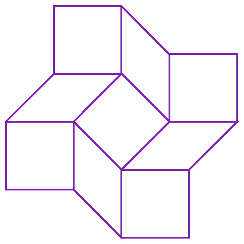
In origami, the square twist is a fold notable in that the crease pattern has 0 degrees of freedom, which means that it should not be able to fold at all. However, in reality, we find that the square twist can exist in either open or closed conformations. This is made possible by the intrinsic nature of paper. As paper used in origami is not completely stiff, the facets of the crease pattern (shown below) can bend and deform. This creates hidden degrees of freedom, allowing the square twist to access its closed conformation. In addition, the folding of the paper along the creases, as well as the bends (deformations) in the facets increases the potential energy of the paper square twist as it folds. Hence, the square twist possess higher potential energy when moving between either configuration, and is most stable in either the fully closed or the fully open configuration[1].
As the square twist is made possible by the deformable nature of paper, it is unknown if a sheet made of DNA, with the same crease pattern, will also be able to access open and closed conformations. To test if the DNA square twist will behave in the same way as the paper square twist, MATLAB was used to model the square twist as it folds from the open conformation to the closed conformation.
Aim
This experiment aimed to model the DNA square twist mathematically and investigate whether the DNA square twist has stable open and closed conformations similar to that of a paper square twist.
Design
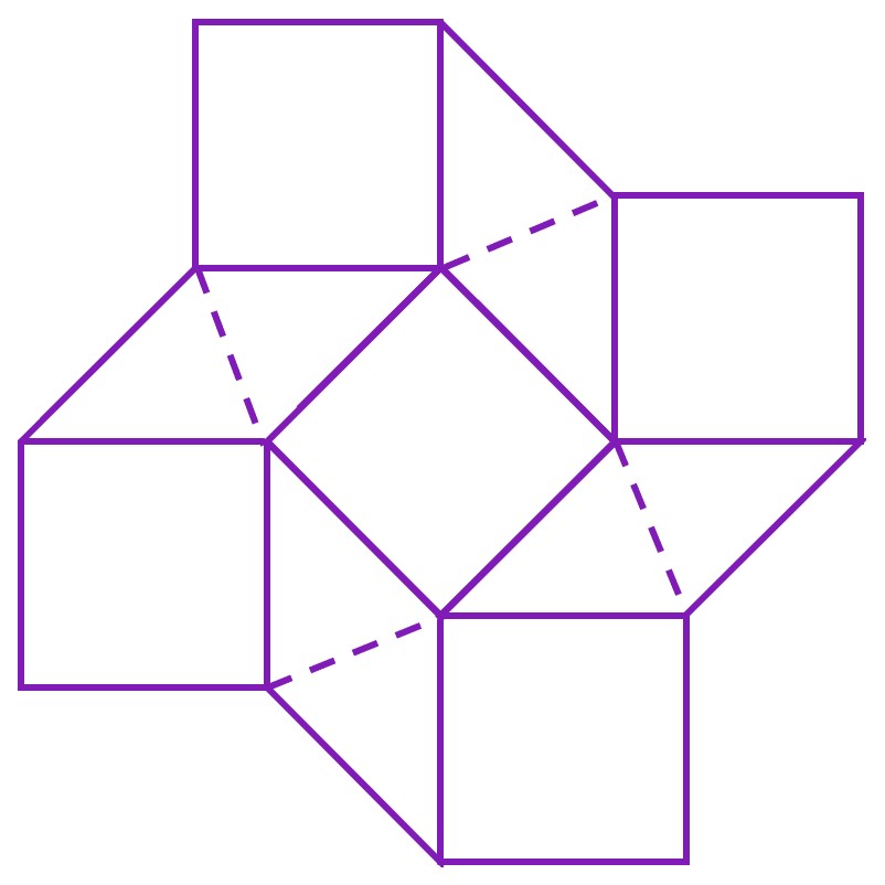
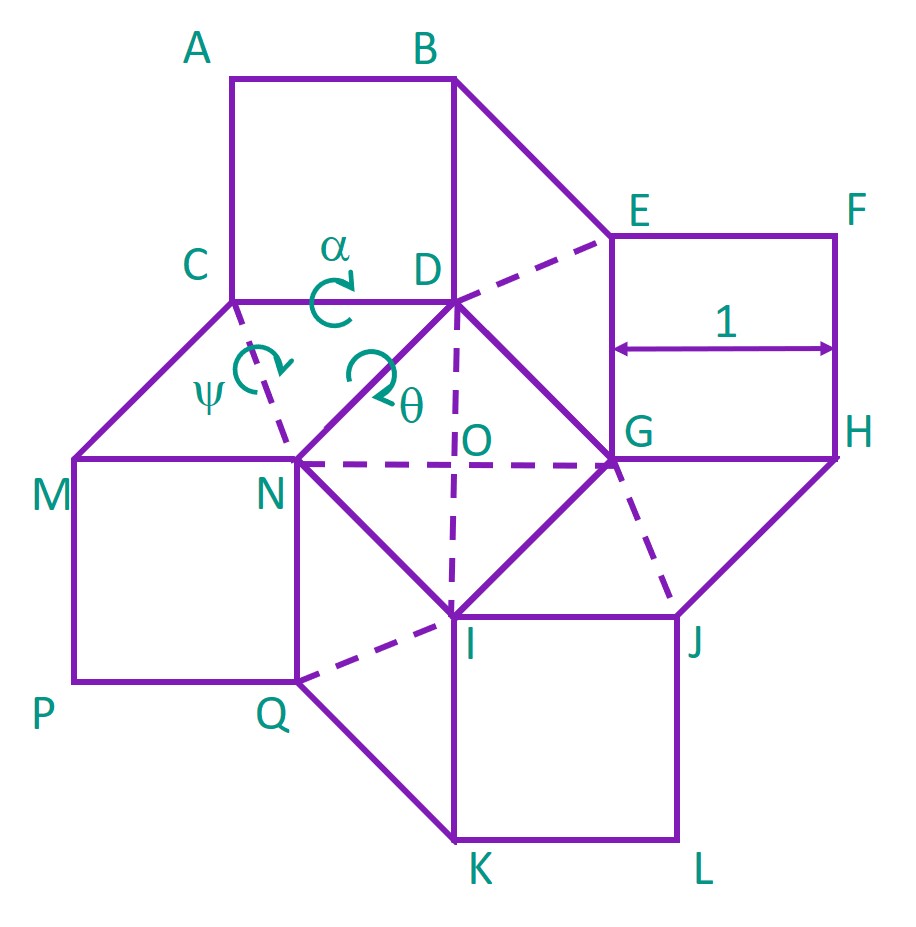
According to Silverberg et al. (2015), deformations in the square twist crease pattern are limited to the rhombus facets. Hence, the square twist can be modelled as a series of rigid square- or triangle- shaped facets, joined along their edges. In the following diagram, the solid lines joining the square and rhombus facets are the creases of the folding pattern, while the dashed lines represent the bends of the rhombus facets.
The elastic potential of the square twist, Utotal, can then be calculated as the sum of the potential energy of the bends and the potential energy of the creases.
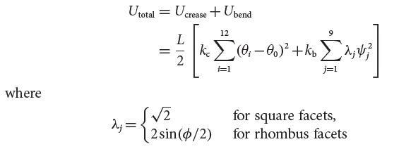
The constant kc is the torsional elastic constant on a crease, while kb is the torsional elastic constant on a bend.
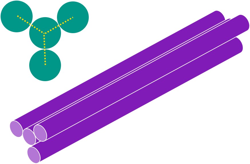
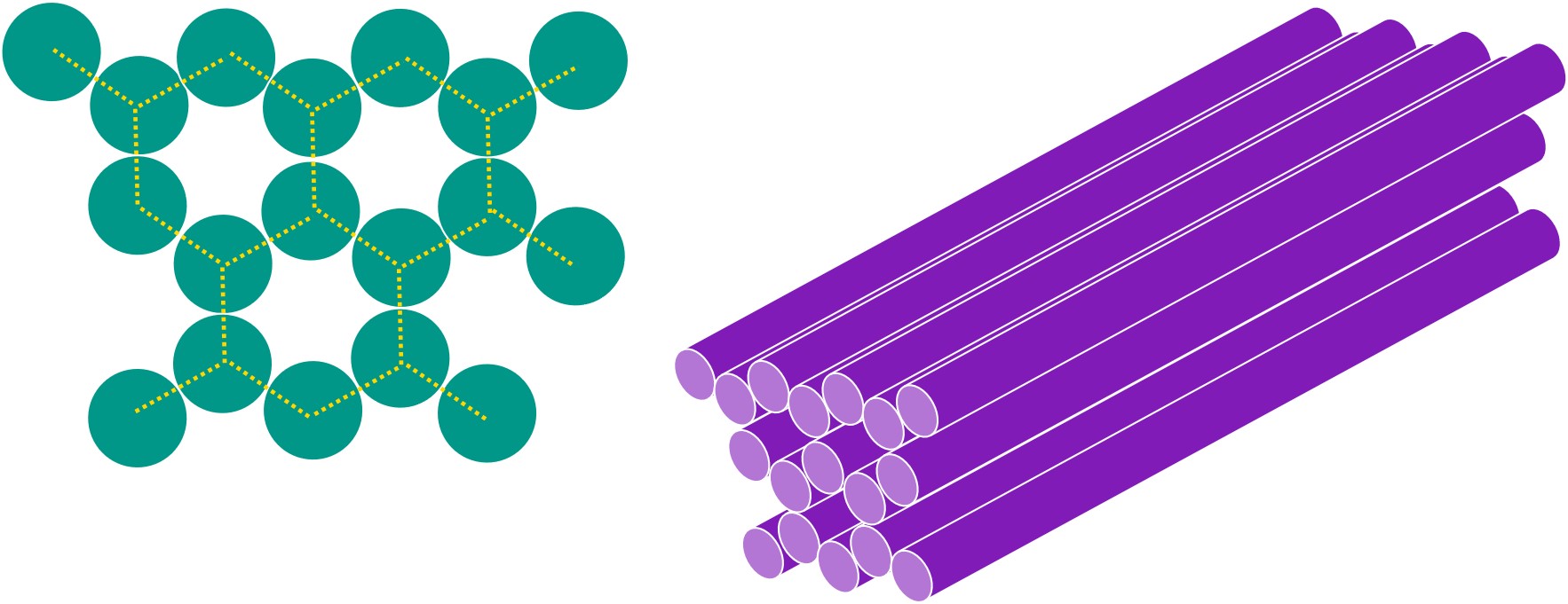
In the DNA square twist, the square and rhombus facets are individual DNA sheets, formed by layers of helices in a honeycomb lattice. An example of a square facet is shown below, where each cylinder is a double-stranded DNA (dsDNA) helix.
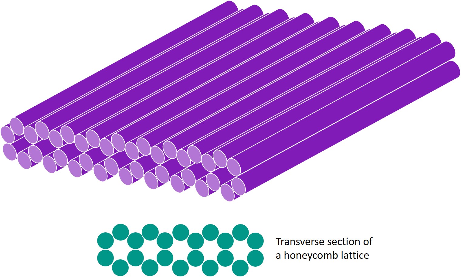
The facets are joined by hinges; lengths of single-stranded DNA (ssDNA). Hence, the creases in the paper folding pattern are replaced by parallel hinges of ssDNA, and kc can be considered the total bending energy of ssDNA. As for the bends, kb can be considered the total bending energy of dsDNA in a honeycomb lattice sheet.
Next, the square twist was modelled in 3-dimensional space. The centre of the central square facet was set at the origin O (0,0,0), and each corner of the pattern was labelled as such. The angles between the facets were also defined as α, ψ and θ as shown.
Using MATLAB, we calculated how the positions of the facets and the angles α and ψ would change as we increased θ from θ to π radians, representing the change from open to closed conformation. These angles were then used to compute the total elastic potential energy of the DNA square twist as it folded.
Results
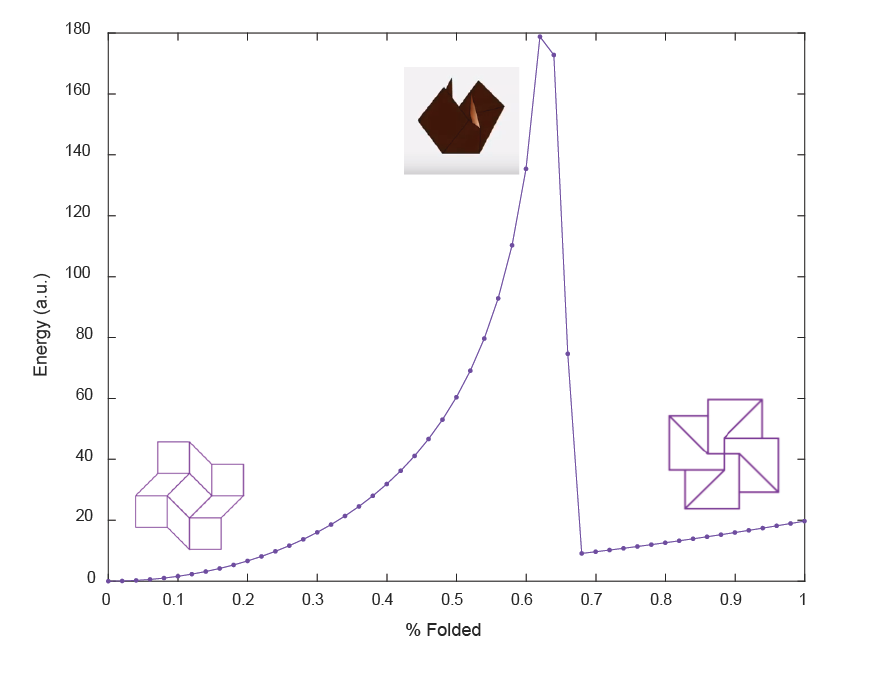
We found that as θ increased to 2 radians, elastic energy increased sharply, which was expected given the increasing creasing and bending. Upon passing this critical value, elastic energy decreases sharply. This means that the elastic energy of the square twist increases as it folds, reaches a maximum, then returns to a minimum. The most stable configurations are the open and closed configurations where energy reaches a minimum.
We used MATLAB code to produce a visualization of the square twist folding process and it’s corresponding energy variations. However, upon physical examination of the square twist folding, some deformation is observed in the peripheral square facets instead of the initial rhombus facets. For this reason, there is no visualization of the square twist folding for theta between 2 and π radians (approximately the last third of folding).
We also used MATLAB code to produce a visualization of the square twist during the folding process.
Conclusions
In this experiment, we observed the changes in elastic energy of a square twist made of DNA as it folded from the open to the closed conformation, and concluded that a square twist made of DNA does indeed have the same properties as a square twist made of paper. In addition, as the initial assumption taken from Silverberg et al. (2015), that bending is constrained to rhombus facets, severely limited the abilities of the model, we have also demonstrated the need for a more sophisticated mathematical model taking into account the bending of the peripheral square facets.
Click to view our MATLAB code.
Stage 2: Designing a one-way hinge
For the DNA square twist to fold successfully, it is important to restrict the angles between the facets. This can be achieved by extending the edge of one facet, forming a one-way hinge. DNA origami was used to design such a hinge. Designs were made in caDNAno and analysed using CanDo. |
Introduction
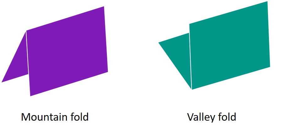
The success of the square twist folding from open to closed conformation is reliant on having creases that can only fold in one direction. Creases identified as mountain folds on the folding pattern must not be allowed to become valley folds, as this causes the sheet to buckle when attempting to fold.
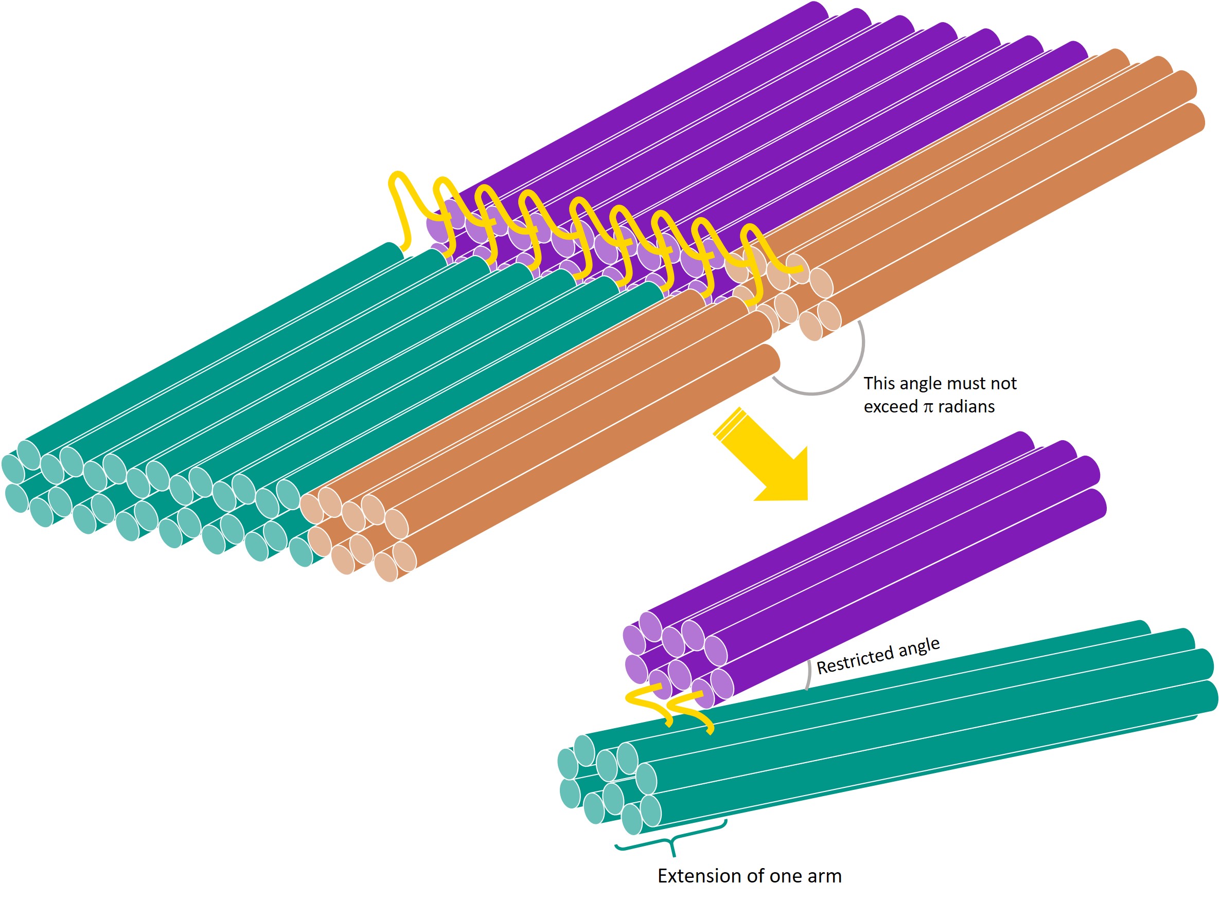
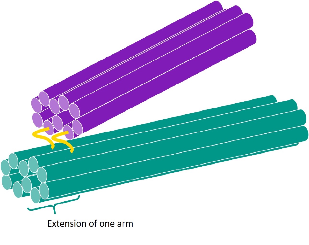
In terms of the DNA square twist, where facets are joined by hinges (strands of ssDNA), this means the angle between 2 facets must be restricted to be less than π radians. This can be done by extending the edge of one facet over the hinge, effectively creating a one-way hinge. As the facets are joined by multiple hinges, for the purpose of this stage, we will only consider a section of the facets, joined by 2 hinges.
To test whether such a one-way hinge can be effectively implemented using DNA, we designed the above structure using DNA origami.
Aim
The aim of this experiment is to design a one-way hinge where the angle between the arms joined by the hinge is restricted to less than π radians.
How DNA origami works
DNA origami is a technique that uses DNA as building blocks to form larger, 3D structures. Specifically, a single, long scaffold, in our case the plasmid M13mp18 (7249 bp), is held together by several shorter staples. As we know the sequence of bases in M13mp18, we must design the sequence of bases in the staples to achieve the intended structure. To understand how we obtain these sequences, some knowledge of the physical structure of DNA is needed. This section thus explains the basic principles behind the structure of DNA origami.
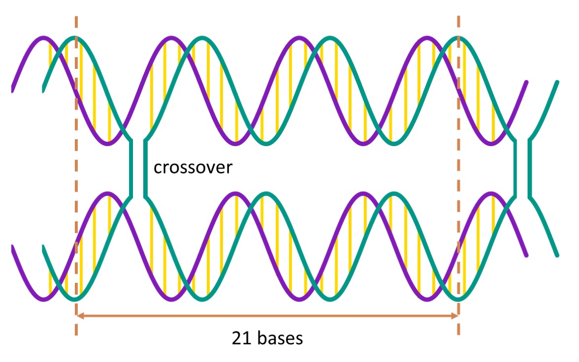
A DNA helix has a helical twist of 10.5 base pairs per turn, which means that the helix turns 240° for every 7 base pairs. When 2 helices are placed side by side, the helices are in greatest proximity every 21 bases. At these points of proximity, the strands in the helices can crossover, thus linking the 2 helices together[2].
If we link one helix to not only 1, but 3 other helices, with crossovers occurring every 7 base pairs, we create the following structure.
We can then repeat this structure to form a honeycomb lattice.
The lengths of the helices in the structure can be changed to obtain specific shapes.
Design
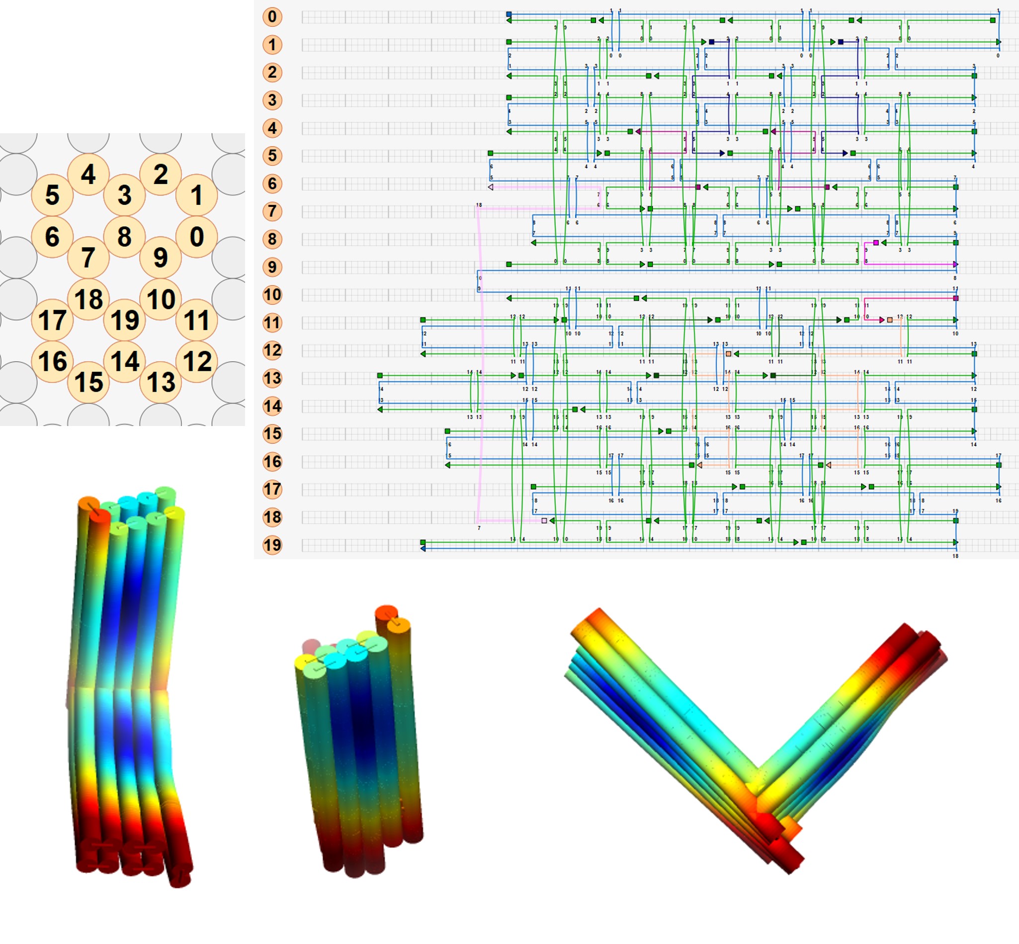
We considered a section of 2 facets, joined by 2 hinges to form a tweezer-like structure. One arm of the tweezer was extended past the hinge, making it a one-way hinge.
Using caDNAno[2], we designed the routing of the scaffold through the structure above, and manually added staples and staple crossovers. Each staple was then inspected and edited to obey the following rules for optimisation of folding:
- Staple length was between 15 and 48 bases
- The ends of each staple must be at least 3 bases away from a staple crossover
6 versions of the one-way hinge were eventually created! Versions 1 and 2 involved only 1 hinge, and was used to experiment with scaffold routing.
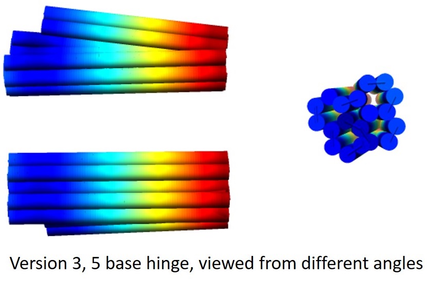
For versions 3 onwards, the arms of the tweezer were linked by 2 hinges. In versions 3, 4 and 5, the positions of the helices were the same, but the number and position of scaffold and staple crossovers between helices were varied. For each version, we also produced 3 sub-versions varying the length of the single-stranded hinge to be 5 base pairs, 10 base pairs, and 24 base pairs., thus yielding 15 sub-versions.
For each sub-version, the design was analysed using CanDo[3,4] to predict its behaviour. Movies generated by CanDo of the thermal fluctuations of the designs suggested that the extension of one arm was indeed able to restrict the range of angles accessible by the other arm.
Using the M13mp18 plasmid (7249 bp) as the scaffold, we obtained the sequence of bases in the staples for each sub-version, and ordered the staples from the DNA. The staples were pooled with the plasmid and folded under different conditions. The folded origami were then purified through agarose gel electrophoresis to identify the optimal folding conditions and the best designs. For more information on the folding process and agarose gel electrophoresis, see Analysis.
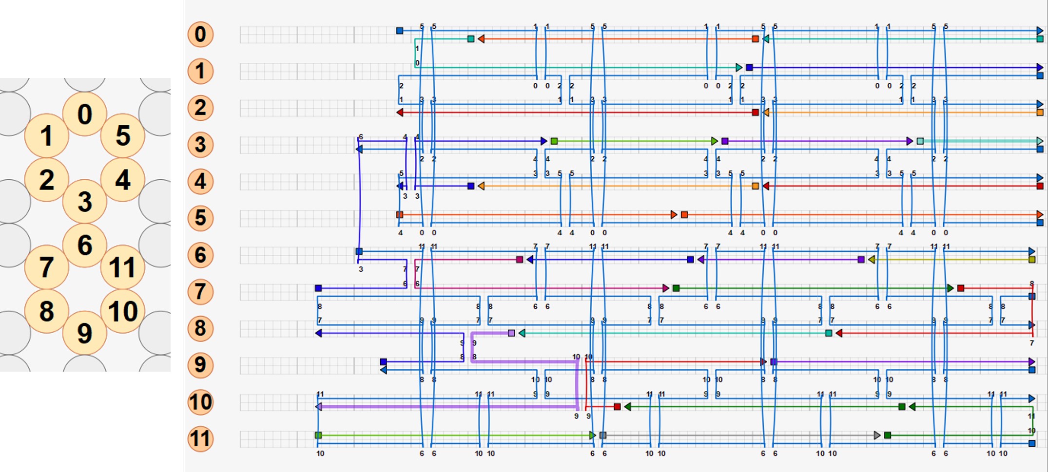
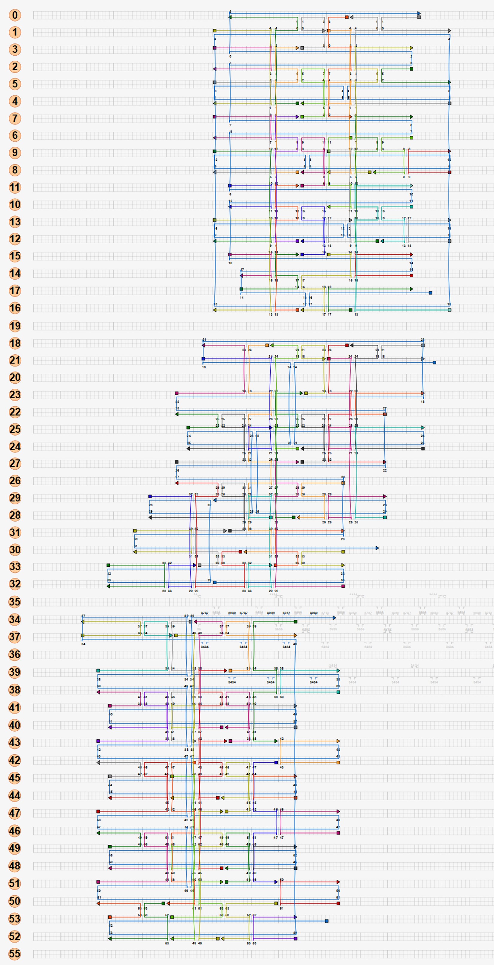
Based on our results of the folded versions 3, 4 and 5, we found that the optimal design was to have 1-2 scaffold crossovers and 3-4 staple crossovers between each pair of adjacent helices, with each hinge being 10 bases in length. We incorporated these parameters, and came up with version 6, for which the scaffolds, staples, and CanDo-generated 3D structure are shown below.
As these 6 versions are only 2 helices thick, they may be difficult to image using transmission electron microscopy. To aid imaging, we create a spare version of the one-way hinge, version 8, that with the same structure as version 8 but twice as thick. We folded versions 6 and 8, purified them and imaged the products. To see how the origami turned out, see our analysis.
To see all our versions of the one-way hinge in all their glory, click here.
Stage 3: Designing a full square twist
Having designed a one-way hinge, the next step is to build the entire square twist out of DNA. Designs were made in caDNAno and analysed using CanDo. |
Introduction
Being able to build a sheet of DNA origami, in the folding pattern of the square twist, is central to our project. To achieve this, we designed square-shaped and rhombus-shaped sheets of DNA origami, and joined these by hinges to create the creases of the folding pattern.
Aim
This experiment aimed to design a square twist made out of DNA.
Design
A single origami structure can only include one scaffold. Hence, the size of the structure is limited by the size of the scaffold, in this case the M13mp18 plasmid (7249 bp). Our first approach was to attempt to build the entire square twist as a single origami structure with a single plasmid routing through the structure. However, preliminary calculations showed that for the M13mp18 plasmid, each side of a square facet in the square twist would have a maximum length of 15.8 nm, or 48 base pairs. The severe restriction of the length would decrease the number of crossovers in the structure, making it extremely unstable and unlikely to fold. Hence, attempting to build the full square twist using a single M13mp18 plasmid unfeasible. However, we attempted a design of the scaffold routing in the full square twist, as this routing could potentially still be used once a larger scaffold is found.
Our second approach was to make the square twist modular. The folding pattern of the square twist can be split into 4 peripheral components and 1 square component, each of which can be synthesized from DNA separately and then joined by adding hinges complementary to the edges of the components.
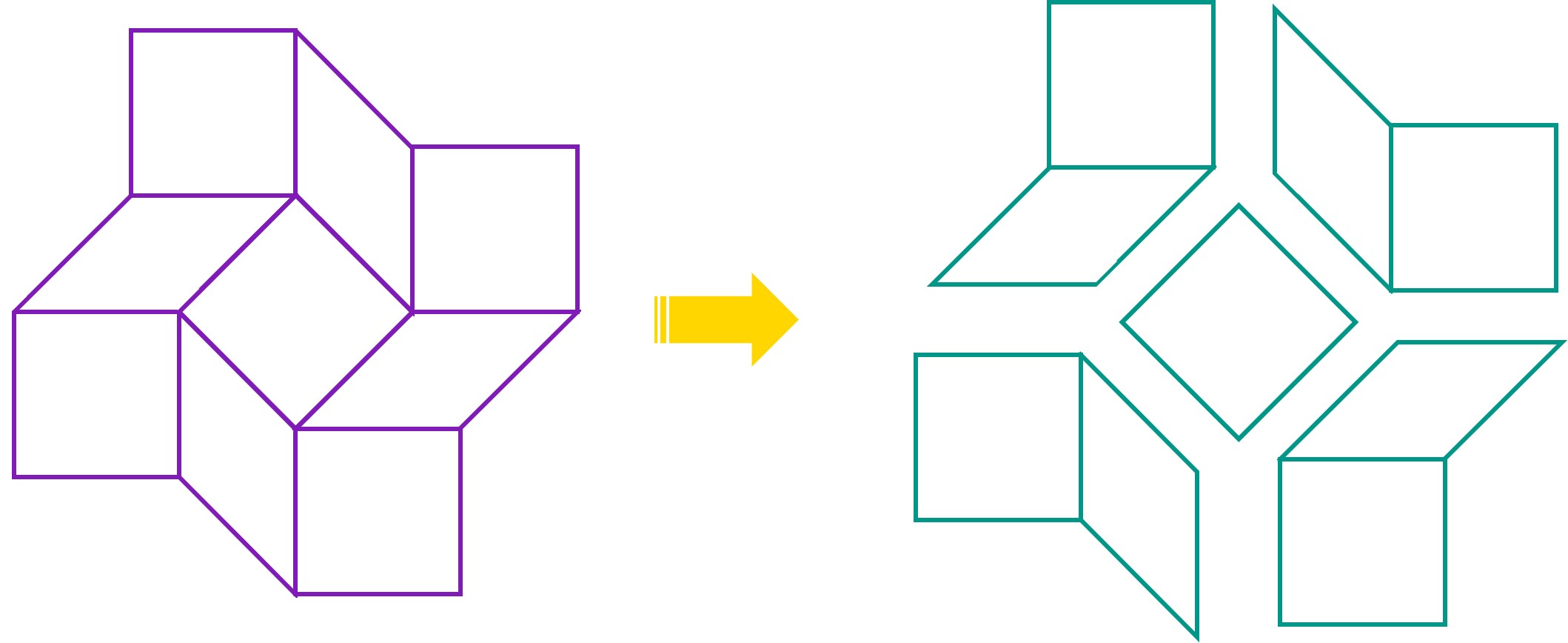
Each side of each component can then be longer, and the structure is likely to be more stable. caDNAno was used to design the peripheral module of the square twist. To reduce dimerisation between origami, a sequence of 5 thymine nucleotides (TTTTT) was added to the staples on the edges of the origami. CanDo analysis was performed on the design.
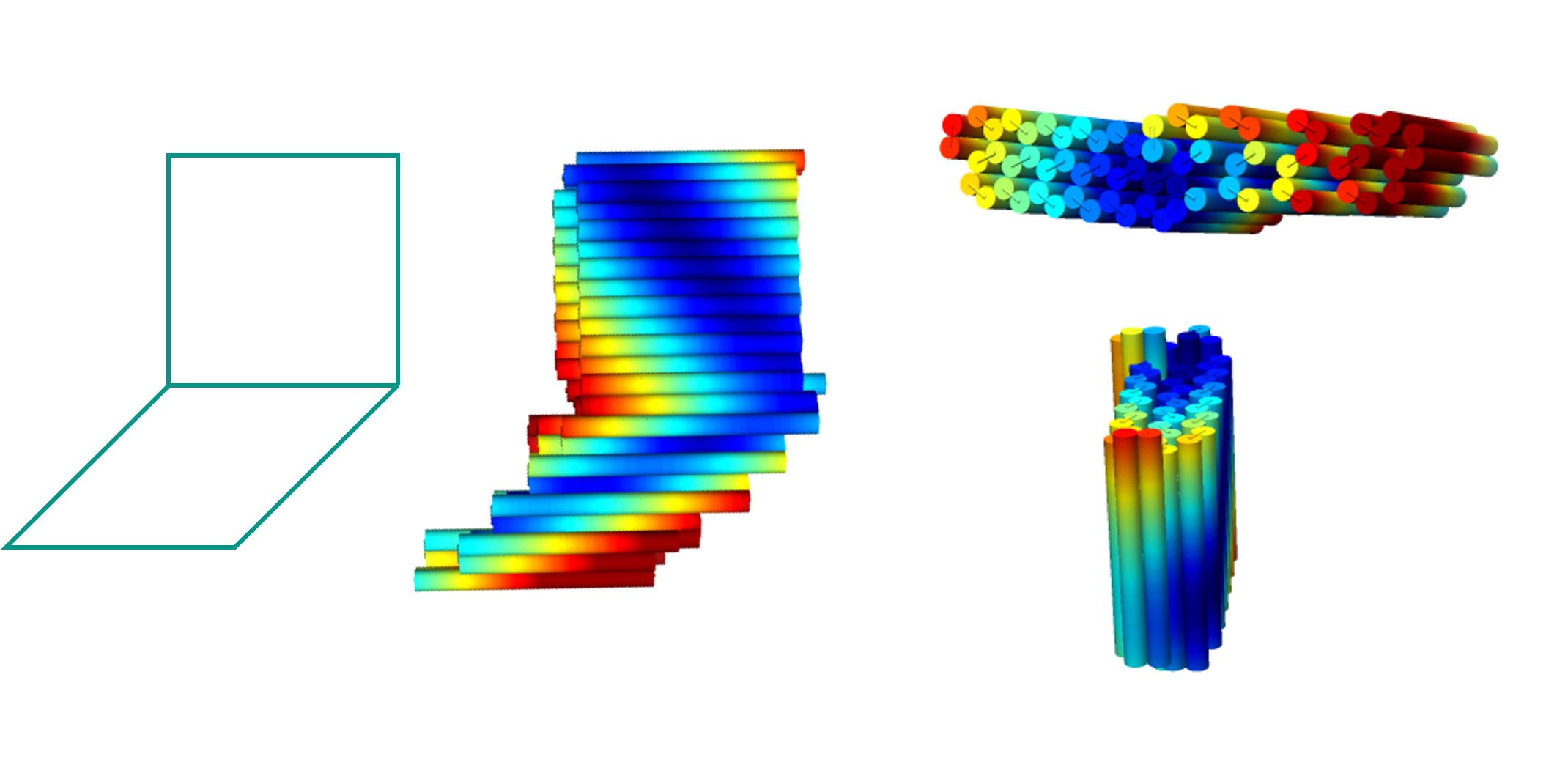
This peripheral module was folded and analysed. To view the results, see Analysis.
To take a closer look at the files involved in this stage, click here.
Stage 4: Demonstrating trigger-induced folding
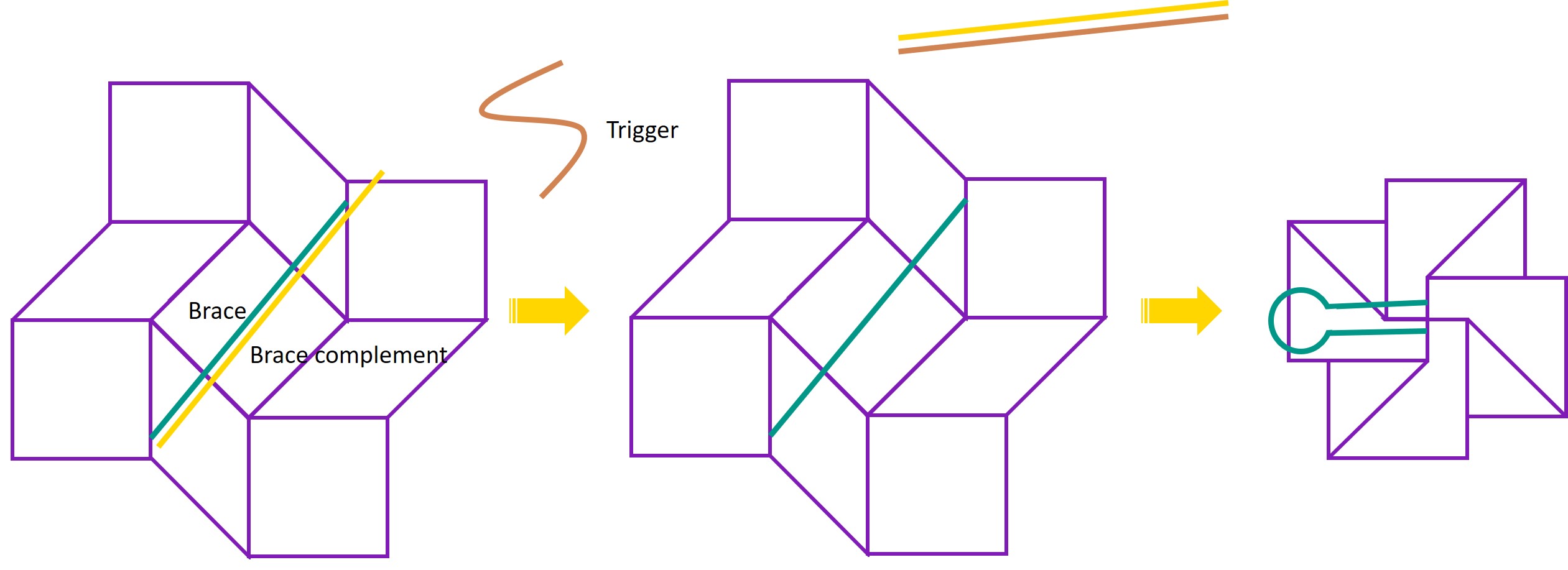
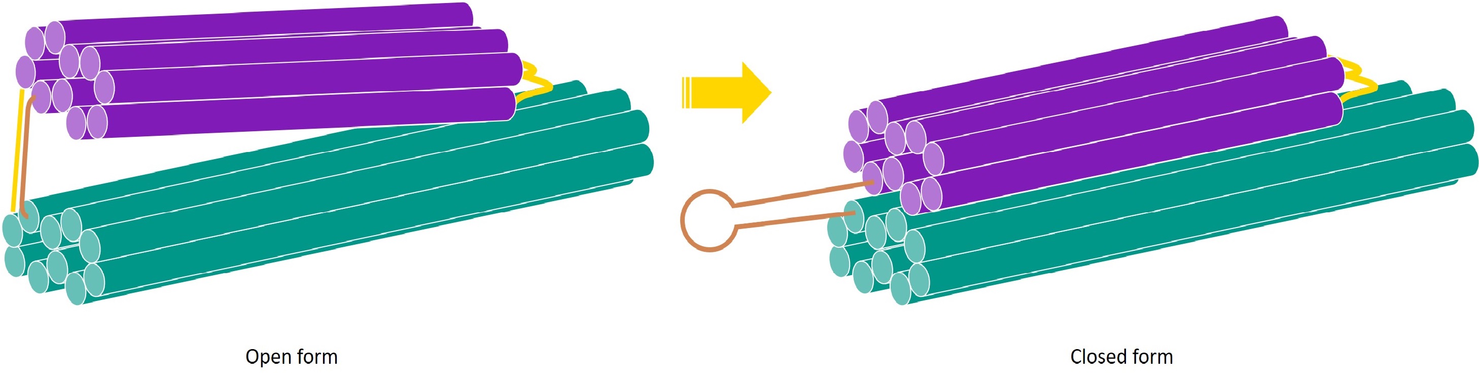
One of the working principles of the detection system is that a trigger DNA sequence causes the square twist to change conformation from open to closed form. This is achieved by adding a brace to the DNA structure, which is initially hybridised to a complement strand. The trigger sequence binds to the complement strand and displaces the brace, leaving the brace single-stranded. The brace then preferentially forms a hairpin. This hairpin formation provides the force needed to change conformations. As we have not yet constructed the full square twist, we instead demonstrate the ability of the trigger and brace to change the conformation of a one-way hinge from open to closed. |
Introduction
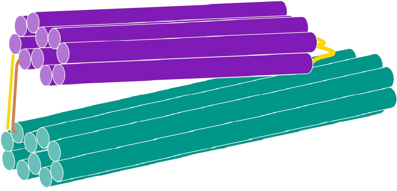
In our system, the amplification system detects the presence of viral DNA and produces an amplified signal in the form of DNA strands. These strands act as a trigger for the detection system, and cause the square twist to change conformation from open to closed form. The trigger does so by interacting with a brace on the square twist. The brace is attached to the square twist and is initially hybridised to a brace complement with a slight overhang. In this hybridised state, the brace holds the square twist open. The trigger strand binds to the brace complement, displacing the brace and leaving the brace single stranded. The brace is designed such that when it is in single-stranded form, it preferentially forms a hairpin. The formation of this hairpin provides the driving force to close the square twist.
For the system to function, we must thus first demonstrate the ability of the trigger to displace the brace complement and cause the brace to form a hairpin, leading to a change in conformation of the DNA structure. As we have not folded the entire square twist yet, the DNA structure that changes conformation in this case is the one-way hinge, instead of the square twist. However, the working principles of the trigger-induced folding are the same, and can be applied to the square twist at a later stage.
Aim
This experiment aimed to design a brace to hold the one-way hinge open at an angle, as well as a brace complement with a slight overhang.
Design
As version 6 of the one-way hinge was designed to be most optimised for folding, it was used as the DNA structure that would change conformation in this experiment. A 60 base brace was designed and joined to 2 of the staples in the one-way hinge to obtain the following structure.
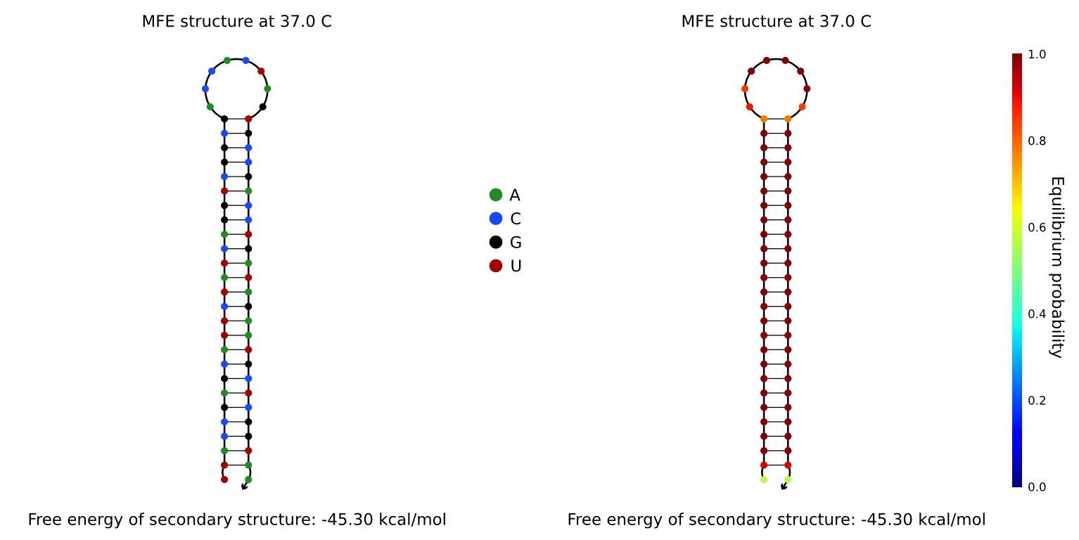
To create a brace that would preferentially form a hairpin when single stranded, we randomly generated a 25 base sequence, named sequence A, and a 10 base sequence, named sequence B. The brace was formed by joining one end of sequence B to sequence A, and the other end of sequence B to the reverse complement of sequence A. The hairpin formation of this brace was checked using NUPACK. The brace was found to form a stable hairpin, and was thus suitable for use.
A brace complement was designed by taking the complement of the brace, and adding a 10 base overhang, the sequence of which was generated randomly. The trigger strand was designed by taking the complement of the brace complement. The brace and brace complement were synthesised and added to the version 6 one-way hinge. To see the results of the brace and trigger, see our Analysis page. (link to analysis page)
For more information on how we designed the brace, click here.
References
- Silverberg JL, Na JH, Evans AA, Liu B, Hull TC, Santangelo SD et al. (2015) Origami structures with a critical transition to bistability arising from hidden degrees of freedom. Nature Materials 14: 389-393.
- Douglas, S.M., Marblestone, A.H., Teerapittayanon, S., Vazquez, A., Church, G.M., Shih, W.M. (2009). Rapid prototyping of 3D DNA-origami shapes with caDNAno. Nucleic Acids Research, 37: 5001-5006.
- Kim, D.N., Kilchherr, F., Dietz, H., Bathe, M. (2012). Quantitative prediction of 3D solution shape and flexibility of nucleic acid nanostructures. Nucleic Acids Research, 40: 2862-2868.
- Castro, C.E., Kilchherr, F., Kim, D.N., Shiao, E.L., Wauer, T., Wortmann, P. et al. (2011). A primer to scaffolded DNA origami. Nature Methods, 8: 221-229.